
ISHIKAWA DIAGRAM CATEGORIES SOFTWARE
It is sometimes easier to construct, and some computer software packages have adopted this form. The cause-effect tree is conceptually similar to the cause-effect diagram. Cause and Effect Tree Diagram Example: Lost Control of Car The interrelationships are generally qualitative and hypothetical.Ī cause-effect diagram is usually prepared as a prelude to developing the data needed to establish causation empirically.For example, if temperature affects both moisture content and physical dimensions, then temperature would appear in both places. One causal factor may appear in several places in the diagram. The interrelationships among the possible causal factors are clearly shown.

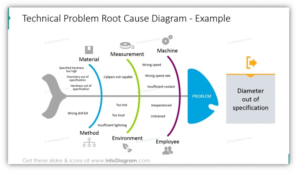
It is a visual representation of the factors that might contribute to an observed effect or phenomenon that is being examined.Cause and Effect Diagram Example: Lost Control of CarĪs we can see from Figure 29, this tool has three prominent basic features: You can probably think of other factors to add to this diagram. Lost control may arise from a mechanical failure that failure may be a brake failure, which, in turn, may come either from fluid loss or from worn pads. The causal relationship can be traced back still more steps in the causal chain if necessary or appropriate. A flat tire may come from a nail, a rock, glass, or a blow-out from material failure. Each of these major categories of causes may, in turn, have multiple causes.
ISHIKAWA DIAGRAM CATEGORIES DRIVER
The phenomenon to be explained is “Lost control of car.” Some of the possible major factors contributing to that lost control are a flat tire, a slippery road, mechanical failures, and driver error. Cause and Effect Diagram ExamplesĪ simple cause-effect diagram is shown in Figure 29. The skeleton becomes the various potential causes and the headers are the column heads from the affinity diagram. The team brainstormed potential causes for this effect. Since the list of issues on a C-E may be very large, the team should use a prioritization or multi-vote technique to narrow the list of potential cause that they desire to investigate farther.Īt the head of the diagram is the “Effect” that the team is investigating. The ideas generated during a brainstorming or affinity process are used to populate the diagram. The C-E Diagram is a fundamental tool utilized in the early stages of an improvement team. When diagnosing the cause of a problem, a cause-effect diagram helps to organize various theories about root causes and presents them graphically. Cause-Effect can also be diagrammed using a tree diagram. A popular type is also referred to as a fishbone or Ishikawa diagram.


 0 kommentar(er)
